
PWM 开发指南
前言
脉宽调制(PWM,Pulse Width Modulation)功能在嵌入式系统中是非常常见的,它是利用微处理器的数字输出来对模拟电路进行控制的一种非常有效的技术,广泛应用在从测量、通信到功率控制与变换的许多领域中。本文主要介绍 Rockchip 平台 PWM 的基本特性、使用方法和常见问题分析。
产品版本
| 芯片名称 | 内核版本 |
|---|---|
| RK3036 | Linux kernel 4.4及以上内核 |
| RK312X/PX35SE | Linux kernel 4.4及以上内核 |
| RK3288 | Linux kernel 4.4及以上内核 |
| RK322X/RK312XH | Linux kernel 4.4及以上内核 |
| RK3308 | Linux kernel 4.4及以上内核 |
| RK322XH/RK332X | Linux kernel 4.4及以上内核 |
| RK3362/PX30 | Linux kernel 4.4及以上内核 |
| RK3368/PX5 | Linux kernel 4.4及以上内核 |
| RK3399 | Linux kernel 4.4及以上内核 |
| RK1808 | Linux kernel 4.4及以上内核 |
| RV1109/RV1126 | Linux kernel 4.19及以上内核 |
| RK356X | Linux kernel 4.19及以上内核 |
| RK3588 | Linux kernel 5.10及以上内核 |
| RV1103/RV1106 | Linux kernel 5.10及以上内核 |
| RK3528 | Linux kernel 4.19及以上内核 |
| RK3562 | Linux kernel 5.10及以上内核 |
| RK3576 | Linux kernel 6.1及以上内核 |
读者对象
本文档(本指南)主要适用于以下工程师: 技术支持工程师
软件开发工程师硬件开发工程师
1. 软件驱动
1. 1 Kernel 驱动
1.1.1 驱动目录
Linux-5.10 及以下版本:
drivers/pwm/pwm-rockchip.c
Linux-6.1 及以上版本:
drivers/pwm/pwm-rockchip.c
drivers/pwm/pwm-rockchip-test.c
Linux-6.1 开始支持了 PWM v4 驱动,Linux-5.10 及以下支持的 PWM v1-v3 共用 v1 的接口,下文中统称为 PWM v1。
Linux-6.1 新增了 test 驱动用于测试功能和定位问题,同时也作为 PWM 各功能的应用示例,需要打开CONFIG_PWM_ROCKCHIP_TEST 以使用。
1.1.2 DTS 配置
在 DTS 中,PWM 节点通常被别的驱动所引用,在其中通过 PWM 框架提供的各接口来配置和使用 PWM,本节以常见的背光驱动为例。PWM v1:
backlight: backlight {
  compatible = "pwm-backlight";
    pwms = <&pwm5 0 25000 0>;
......
};
PWM v4:
backlight: backlight {
   compatible = "pwm-backlight";
   pwms = <&pwm1_6ch_1 0 25000 0>;
......
};
PWM v1 和 PWM v4 节点的命名方式有所不同:
PWM v1 为 pwmX,实际对应的控制器 id 为 X / 4,通道 id 为 X % 4。
PWM v4 为 pwmX_Ych_Z,X 表示控制器 id ,Y 表示当前控制器支持的通道总数,Z 表示通道 id 。
Linux-4.4 及以上内核 PWM 节点支持的参数个数从 Linux-3.10 的 2 个提升到 3 个,具体个数与 PWM 节点的 #pwm-cells 属性相对应, 参考文档 Documentation/devicetree/bindings/pwm/pwm.txt中有详细的说明,此处仅对各参数作简要说明:
参数 1,表示 index (per-chip index of the PWM to request),值固定为 0。Rockchip 平台的每个 PWM channel 对应一个 PWM device,且每个 device 只有一个 chip。
参数 2,表示 PWM 输出波形的 period,单位为 ns。示例中的 25000 ns 换算为频率即为 40KHz。
参数 3,表示可选参数 polarity,默认为0,若要翻转极性则配为 PWM_POLARITY_INVERTED。
2 功能支持
SOC |
PWM version |
continuous |
oneshot |
capture |
global control |
output offset |
counter |
frequency meter |
IR output |
IR input |
wave generator |
|---|---|---|---|---|---|---|---|---|---|---|---|
RK3036 |
v1 |
√ |
√ |
√ |
× |
× |
× |
× |
× |
√ |
× |
RK312X/PX3SE |
v1 |
√ |
√ |
√ |
× |
× |
× |
× |
× |
× |
× |
RK3288 |
v1 |
√ |
√ |
√ |
× |
× |
× |
× |
× |
× |
× |
RK322X/RK312XH |
v1 |
√ |
√ |
√ |
× |
× |
× |
× |
× |
× |
× |
RK3308 |
v2 |
√ |
√ |
√ |
× |
× |
× |
× |
√ |
√ |
√ |
RK322XH/RK332X |
v2 |
√ |
√ |
√ |
× |
× |
× |
× |
√ |
√ |
√ |
RK3326/PX30 |
v2 |
√ |
√ |
√ |
× |
× |
× |
× |
√ |
√ |
√ |
RK3368/PX5 |
v1 |
√ |
√ |
√ |
× |
× |
× |
× |
× |
√ |
× |
RK3399 |
v1 |
√ |
√ |
√ |
× |
× |
× |
× |
× |
√ |
× |
RK3288 |
v1 |
√ |
√ |
√ |
× |
× |
× |
× |
× |
× |
× |
RK1808 |
v2 |
√ |
√ |
√ |
× |
× |
× |
× |
√ |
√ |
√ |
RV1109/RV1126 |
v2 |
√ |
√ |
√ |
× |
× |
× |
× |
√ |
√ |
√ |
RK356X |
v2 |
√ |
√ |
√ |
× |
× |
× |
× |
√ |
√ |
√ |
RK3588 |
v3 |
√ |
√ |
√ |
√ |
√ |
√ |
√ |
√ |
√ |
√ |
RV1103/RV1106 |
v2 |
√ |
√ |
√ |
× |
× |
× |
× |
√ |
√ |
√ |
RK3528 |
v3 |
√ |
√ |
√ |
√ |
√ |
√ |
√ |
√ |
√ |
√ |
RK3562 |
v3 |
√ |
√ |
√ |
√ |
√ |
√ |
√ |
√ |
√ |
√ |
RK3576 |
v4 |
√ |
√ |
√ |
√ |
√ |
√ |
√ |
√ |
√ |
√ |
3 应用说明
对于 PWM kernel 和 user space 的应用方法在Documentation/devicetree/bindings/pwm/pwm.txt 已有说明,本节主要针对Rockchip 平台的 PWM特性进一步展开。
3.1 Kernel driver
Kernel 驱动中若要使用 PWM,可以参考 [《DTS 配置》]{.underline}章节中backlight 驱动的配置方法,在驱动节点下添加 pwms 属性,再通过如下接口get/put PWM 设备:
struct pwm_device *pwm_get(struct device *dev, const char *con_id);
void pwm_put(struct pwm_device *pwm);

struct pwm_device *devm_pwm_get(struct device *dev, const char *con_id);
struct pwm_device *devm_fwnode_pwm_get(struct device *dev, struct fwnode_handle *fwnode, const char *con_id);
具体实现及功能说明详见 include/linux/pwm.h 和 drivers/pwm/core.c。
PWM 框架提供的接口(摘自 Linux-5.10,Linux-6.1 上已经将 legacy drivers相关的接口全部删除):
/**
* struct pwm_ops - PWM controller operations
* @request: optional hook for requesting a PWM
* @free: optional hook for freeing a PWM
* @capture: capture and report PWM signal
* @apply: atomically apply a new PWM config
* @get_state: get the current PWM state. This function is only
* called once per PWM device when the PWM chip is
* registered.
* @get_output_type_supported: get the supported output type of this PWM
* @owner: helps prevent removal of modules exporting active PWMs
* @config: configure duty cycles and period length for this PWM
* @set_polarity: configure the polarity of this PWM
* @enable: enable PWM output toggling
* @disable: disable PWM output toggling
*/
struct pwm_ops {
int (*request)(struct pwm_chip *chip, struct pwm_device *pwm);
void (*free)(struct pwm_chip *chip, struct pwm_device *pwm);
int (*capture)(struct pwm_chip *chip, struct pwm_device *pwm,
struct pwm_capture *result, unsigned long timeout);
int (*apply)(struct pwm_chip *chip, struct pwm_device *pwm,
const struct pwm_state *state);
void (*get_state)(struct pwm_chip *chip, struct pwm_device *pwm,
struct pwm_state *state);
int (*get_output_type_supported)(struct pwm_chip *chip,
struct pwm_device *pwm);
struct module *owner;
/* Only used by legacy drivers */
int (*config)(struct pwm_chip *chip, struct pwm_device *pwm,
int duty_ns, int period_ns);
int (*set_polarity)(struct pwm_chip *chip, struct pwm_device *pwm,
enum pwm_polarity polarity);
int (*enable)(struct pwm_chip *chip, struct pwm_device *pwm);
void (*disable)(struct pwm_chip *chip, struct pwm_device *pwm);
ANDROID_KABI_RESERVE(1);
};
Linux-4.4 及以上内核不再实现 config、enable 和 disable 等接口,而改为实现 apply。
目的在于可以用 int pwm_apply_state(struct pwm_device *pwm, const struct pwm_state *state)函数,通过struct_pwm_state 来 atomic 改变 PWM 设备的多个参数。
/*
* struct pwm_state - state of a PWM channel
* @period: PWM period (in nanoseconds)
* @duty_cycle: PWM duty cycle (in nanoseconds)
* @polarity: PWM polarity
* @enabled: PWM enabled status
* @usage_power: If set, the PWM driver is only required to maintain the power
* output but has more freedom regarding signal form.
* If supported, the signal can be optimized, for example to
* improve EMI by phase shifting individual channels.
*/
struct pwm_state {
u64 period;
u64 duty_cycle;
enum pwm_polarity polarity;
#ifdef CONFIG_PWM_ROCKCHIP_ONESHOT
u64 oneshot_count;
u32 oneshot_repeat;
u64 duty_offset;
#endif /* CONFIG_PWM_ROCKCHIP_ONESHOT */
bool enabled;
bool usage_power;
};
PWM 的基本功能,包括 continous、oneshot 和 caputure 等, 可以通过 PWM框架提供的接口来应用,而 Rockchip 平台 PWM v4 支持的frequency meter、counter 和 wave generator 等功能需要引用头文件include/linux/pwm-rockchip.h来使用。下面对各功能及其应用进行具体的介绍,也可以参考 demo 驱动drivers/pwm/pwm-rockchip-test.c。
3.1.1 Continous
连续输出模式,支持持续输出指定占空比的 PWM 波形。
3.1.2 Oneshot
单次输出模式,支持输出指定个数的 PWM 波形。Kernel 中需要打开 CONFIG_PWM_ROCKCHIP_ONESHOT 配置。
pwm_get_state(pdev, &state);
state.period = period;
state.duty_cycle = duty;
state.duty_offset = duty_offset;
state.polarity = polarity;
state.oneshot_count = rpt_first;
state.oneshot_repeat = rpt_second;
pwm_apply_state(pdev, &state);
oneshot_count 表示输出指定占空比的波形个数,在 PWM v4 上扩展了波形个数的上限,实际输出波形个数为 oneshot_repeat * oneshot_count。
oneshot 模式在输出结束后会产生中断,用户可以按需在drivers/pwm/pwm-rockchip-irq-callbacks.h 中断处理函数中添加相应逻辑:
static void rockchip_pwm_oneshot_callback(struct pwm_device *pwm, struct pwm_state *state)
{
/*
* If you want to enable oneshot mode again, config and call
* pwm_apply_state().
*
* struct pwm_state new_state;
*
* pwm_get_state(pwm, &new_state);
* new_state.enabled = true;
* ......
* pwm_apply_state(pwm, &new_state);
*
*
3.1.3 Capture
输入捕获模式,支持计算输入波形高低电平的持续时间。
pwm_capture(pdev, &cap_res, timeout_ms);
在 timeout_ms 后返回计算的结果 cap_res:
/**
* struct pwm_capture - PWM capture data
* @period: period of the PWM signal (in nanoseconds)
* @duty_cycle: duty cycle of the PWM signal (in nanoseconds)
*/
struct pwm_capture {
unsigned int period;
unsigned int duty_cycle;
};
3.1.4 Global control
全局控制模式,支持多通道配置的同步更新,结合 continous/oneshot mode 可以实现输出同步、互补输出等功能。
// join the global control group
rockchip_pwm_global_ctrl(pdev0, PWM_GLOBAL_CTRL_JOIN);
rockchip_pwm_global_ctrl(pdev1, PWM_GLOBAL_CTRL_JOIN);
rockchip_pwm_global_ctrl(pdev2, PWM_GLOBAL_CTRL_JOIN);
// assign one channel to obtain the permission of global control
rockchip_pwm_global_ctrl(pdev0, PWM_GLOBAL_CTRL_GRANT);
// use pwm_apply_state() to update configurations for each channel
......
// update the configs for all channels in group
rockchip_pwm_global_ctrl(pdev0, PWM_GLOBAL_CTRL_UPDATE);
// enable all channels in group
rockchip_pwm_global_ctrl(pdev0, PWM_GLOBAL_CTRL_ENABLE);
// reclaim the permission of global control
rockchip_pwm_global_ctrl(pdev0, PWM_GLOBAL_CTRL_RECLAIM);
// exit the global control group
rockchip_pwm_global_ctrl(pdev0, PWM_GLOBAL_CTRL_EXIT);
rockchip_pwm_global_ctrl(pdev1, PWM_GLOBAL_CTRL_EXIT);
rockchip_pwm_global_ctrl(pdev2, PWM_GLOBAL_CTRL_EXIT);
global control 模式中各指令的说明:
/**
* enum rockchip_pwm_global_ctrl_cmd - commands for pwm global ctrl
* @PWM_GLOBAL_CTRL_JOIN: join the global control group
* @PWM_GLOBAL_CTRL_EXIT: exit the global control group
* @PWM_GLOBAL_CTRL_GRANT: obtian the permission of global control
* @PWM_GLOBAL_CTRL_RECLAIM: reclaim the permission of global control
* @PWM_GLOBAL_CTRL_UPDATE: update the configs for all channels in group
* @PWM_GLOBAL_CTRL_ENABLE: enable all channels in group
* @PWM_GLOBAL_CTRL_DISABLE: disable all channels in group
*/
enum rockchip_pwm_global_ctrl_cmd {
PWM_GLOBAL_CTRL_JOIN,
PWM_GLOBAL_CTRL_EXIT,
PWM_GLOBAL_CTRL_GRANT,
PWM_GLOBAL_CTRL_RECLAIM,
PWM_GLOBAL_CTRL_UPDATE,
PWM_GLOBAL_CTRL_ENABLE,
PWM_GLOBAL_CTRL_DISABLE,
};
3.1.5 Output offset
输出偏移模式,支持 PWM 输出波形偏移指定的时间,通常结合 global control 在 oneshot 模式下使用,对应offset 参数,可以参考 oneshot 模式说明 。
3.1.6 Counter
输入计数模式,支持计算输入波形的个数。
rockchip_pwm_set_counter(pdev, PWM_COUNTER_INPUT_FROM_IO, true);
msleep(timeout_ms);
rockchip_pwm_set_counter(pdev, 0, false);
rockchip_pwm_get_counter_result(pdev, &counter_res, true);
在 timeout_ms 后关闭 counter 并获取计数结果 counter_res:
3.1.7 Frequency meter
频率计模式,支持计算输入波形的频率。
rockchip_pwm_set_freq_meter(pdev, timeout_ms, PWM_COUNTER_INPUT_FROM_IO, &freq_hz);
在 timeout_ms 后返回计算的结果 freq_hz。
3.1.8 IR output
驱动暂不支持。
3.1.9 IR input
详见文档《Rockchip_Developer_Guide_PWM_IR_CN》,对应内核驱动为driver/input/remotectl/rockchip_pwm_remotectl.c。
3.1.10 Wave generator
波形发生器模式,支持根据 wave table 中的配置输出指定波形。
// setup the duty table
for (i = 0; i < PWM_TABLE_MAX; i++)
table[i] = i * PWM_WAVE_STEP;
duty_table.table = table;
duty_table.offset = (channel_id % 3) * PWM_TABLE_MAX;
duty_table.len = PWM_TABLE_MAX;
// setup the repeat time for each parameter in table
wave_config.rpt = PWM_WAVE_RPT;
// setup the clk rate
wave_config.clk_rate = 400000;
// If duty_en is true, the wave will get duty config from table each PWM_WAVE_RPT period, and the same to
period_en
wave_config.duty_table = &duty_table;
wave_config.period_table = NULL;
wave_config.enable = enable;
wave_config.duty_en = true;
wave_config.period_en = false;
// setup the width_mode and update_mode
wave_config.width_mode = PWM_WIDTH_MODE;
wave_config.update_mode = PWM_WAVE_INCREASING_THEN_DECREASING;
// setup the start and end index in duty/period table
wave_config.duty_max = (channel_id % 3 + 1) * PWM_TABLE_MAX - 1;
wave_config.duty_min = (channel_id % 3) * PWM_TABLE_MAX;
wave_config.period_max = 0;
wave_config.period_min = 0;
wave_config.offset = 0;
// setup the middle index to change table config in interrupt if needed.
wave_config.middle = PWM_TABLE_MAX / 2;
rockchip_pwm_set_wave(pdev, &wave_config);
// enable the continous mode
pwm_get_state(pdev, &state);
state.period = period;
state.duty_cycle = duty;
state.polarity = polarity;
state.enabled = enable;
pwm_apply_state(pdev, &state);
wave 模式相关的配置及说明如下:
/**
* enum rockchip_pwm_wave_table_width_mode - element width of pwm wave table
* @PWM_WAVE_TABLE_8BITS_WIDTH: each element in table is 8bits
* @PWM_WAVE_TABLE_16BITS_WIDTH: each element in table is 16bits
*/
enum rockchip_pwm_wave_table_width_mode {
PWM_WAVE_TABLE_8BITS_WIDTH,
PWM_WAVE_TABLE_16BITS_WIDTH,
};
/**
* enum rockchip_pwm_wave_update_mode - update mode of wave generator
* @PWM_WAVE_INCREASING:
* The wave table address will wrap back to minimum address when increase to
* maximum and then increase again.
* @PWM_WAVE_INCREASING_THEN_DECREASING:
* The wave table address will change to decreasing when increasing to the maximum
* address. it will return to increasing when decrease to the minimum value.
*/
enum rockchip_pwm_wave_update_mode {
PWM_WAVE_INCREASING,
PWM_WAVE_INCREASING_THEN_DECREASING,
};
/**
* struct rockchip_pwm_wave_config - wave generator config object
* @duty_table: the wave table config of duty
* @period_table: the wave table config of period
* @enable: enable or disable wave generator
* @duty_en: to update duty by duty table or not
* @period_en: to update period by period table or not
* @clk_rate: the dclk rate in wave generator mode
* @rpt: the number of repeated effective periods
* @width_mode: the width mode of wave table
* @update_mode: the update mode of wave generator
* @duty_max: the maximum address of duty table
* @duty_min: the minimum address of duty table
* @period_max: the maximum address of period table
* @period_min: the minimum address of period table
* @offset: the initial offset address of duty and period
* @middle: the middle address of duty and period
* @max_hold: the time to stop at maximum address
* @min_hold: the time to stop at minimum address
* @middle_hold: the time to stop at middle address
*/
struct rockchip_pwm_wave_config {
struct rockchip_pwm_wave_table *duty_table;
struct rockchip_pwm_wave_table *period_table;
bool enable;
bool duty_en;
bool period_en;
unsigned long clk_rate;
u16 rpt;
u32 width_mode;
u32 update_mode;
u32 duty_max;
u32 duty_min;
u32 period_max;
u32 period_min;
u32 offset;
u32 middle;
u32 max_hold;
u32 min_hold;
u32 middle_hold;
};
PWM v4 在 wave generator 模式下有 768 * 8bit 大小的空间用于存储 duty/period 配置,开启 duty_en/period_en 后每 rpt 个周期就会从duty_table/period_table 中 duty_min + offset/period_min + offset索引处取新的配置值(单位:ns),直到 duty_max/period_max为止。接着会根据 update_mode 重新进入下一次循环,如果是 oneshot 模式下 oneshot_repeat 次循环后就会停止,而 continous 模式将会持续输出直到手动停止。
wave 支持 width_mode 的切换(768 * 8bit 和 384 * 16bit),相同工作时钟 dclk 下,16bit 模式会支持更大的 duty/period 配置。
在配置的 middle 和 max 索引处会产生中断,用户可以按需在 drivers/pwm/pwm-rockchip-irq-callbacks.h 中断处理函数中添加相应逻辑:
static void rockchip_pwm_wave_middle_callback(struct pwm_device *pwm)
{
   /*
   * If you want to update the configuration of wave table, set
   * struct rockchip_pwm_wave_table and call rockchip_pwm_set_wave().
   *
   * struct rockchip_pwm_wave_config wave_config;
   * struct rockchip_pwm_wave_table duty_table;
   *
   * //fill the duty table
   * ......
   * wave_config.duty_table = &duty_table;
   * wave_config.enable = true;
   * rockchip_pwm_set_wave(pwm, &wave_config);
   *
   */
}
static void rockchip_pwm_wave_max_callback(struct pwm_device *pwm)
{
   /*
   * If you want to update the configuration of wave table, set
   * struct rockchip_pwm_wave_table and call rockchip_pwm_set_wave().
   *
   * struct rockchip_pwm_wave_config wave_config;
   * struct rockchip_pwm_wave_table duty_table;
   *
   * //fill the duty table
   * ......
   * wave_config.duty_table = &duty_table;
   * wave_config.enable = true;
   * rockchip_pwm_set_wave(pwm, &wave_config);
   *
   */
};
3.1.11 Biphasic counter
双向计数器模式,支持 mode0-mode4 五种计数模式(详见 TRM 中 PWM 章节的描述),mode0 下可以作为上述的 counter 和 freqency meter使用。
biphasic_config.enable = true;
biphasic_config.is_continuous = false;
biphasic_config.mode = biphasic_mode;
biphasic_config.delay_ms = timeout_ms;
rockchip_pwm_set_biphasic(pdev, &biphasic_config, &biphasic_res);
biphasic_config 各参数说明如下:
   /**
* struct rockchip_pwm_biphasic_config - biphasic counter config object
* @enable: enable: enable or disable biphasic counter
* @is_continuous: biphascic counter will not stop at the end of timer in continuous mode
* @mode: the mode of biphasic counter
* @delay_ms: time to wait, in milliseconds, before getting biphasic counter result
*/
struct rockchip_pwm_biphasic_config {
   bool enable;
   bool is_continuous;
   u8 mode;
   u32 delay_ms;
};
非 continous 模式下,timeout_ms 后返回计数的结果biphasic_res。
continous 模式下,计数在手动关闭前将持续进行,可以通过实时获取计数结果。
biphasic counter 模式说明:
   /**
   * enum rockchip_pwm_biphasic_mode - mode of biphasic counter
   * @PWM_BIPHASIC_COUNTER_MODE0: single phase increase mode with A-phase
   * @PWM_BIPHASIC_COUNTER_MODE1: single phase increase/decrease mode with A-phase
   * @PWM_BIPHASIC_COUNTER_MODE2: dual phase with A/B-phase mode
   * @PWM_BIPHASIC_COUNTER_MODE3: dual phase with A/B-phase 2 times frequency mode
   * @PWM_BIPHASIC_COUNTER_MODE4: dual phase with A/B-phase 4 times frequency mode
   */
   enum rockchip_pwm_biphasic_mode {
      PWM_BIPHASIC_COUNTER_MODE0,
      PWM_BIPHASIC_COUNTER_MODE1,
      PWM_BIPHASIC_COUNTER_MODE2,
      PWM_BIPHASIC_COUNTER_MODE3,
      PWM_BIPHASIC_COUNTER_MODE4,
      PWM_BIPHASIC_COUNTER_MODE0_FREQ,
   };
PWM_BIPHASIC_COUNTER_MODE0 等价于 counter 功能,而 PWM_BIPHASIC_COUNTER_MODE0_FREQ 等价于freqencymeter功能。
3.2 User space
PWM 框架在 /sys/class/pwm/ 目录下提供了用户层接口,详见drivers/pwm/sysfs.c,PWM 驱动加载成功后,会在其下生成 pwmchipX目录,如pwmchip0、pwmchip1 等,此处的 X 与 PWM 的控制器或通道 id 无关,仅与PWM 设备的 probe 顺序有关。
root@linaro-alip:/# cat /sys/class/pwm/pwmchip0/
device/ export npwm power/ subsystem/ uevent unexport
向 export 节点写入 Y,会在当前目录下产生一个 pwmY 目录,由于 Rockchip 平台每个 PWM device 只有一个 chip,Y 值只能为 0。反之,向unexport 节点写入 Y 就会删除 pwmY 目录。
pwmY 目录下有以下几个可操作的节点:
enable:写入 1 使能 PWM,写入 0 关闭 PWM;
polarity:有 normal 或 inversed 两个参数选择,对应 PWM 的极性配置 PWM_POLARITY_NORMAL/PWM_POLARITY_INVERSED; duty_cycle:在 normal 模式下,表示一个周期内高电平持续的时间(单位:ns),在 reversed 模式下,表示一个周期中低电平持续的时间(单位:ns);
period:表示 PWM 波形的周期(单位:ns);
oneshot_count:需开启 CONFIG_PWM_ROCKCHIP_ONESHOT,表示 oneshot 模式的 PWM 波形个数;
oneshot_repeat:需开启 CONFIG_PWM_ROCKCHIP_ONESHOT 且仅 PWM v4 支持,表示 oneshot 模式重复的次数,最后输出的波形个数为 oneshot_repeat * oneshot_count;
duty_offset:需开启 CONFIG_PWM_ROCKCHIP_ONESHOT,表示 PWM 输出波形偏移的时间(单位:ns);
capture:使能 capture 模式,获取输入波形高低电平的时长(单位:ns)。
3.2.1 Continous
cd /sys/class/pwm/pwmchip0/
echo 0 > export
cd pwm0
echo 10000 > period
echo 5000 > duty_cycle
echo normal > polarity
echo 1 > enable
3.2.2 Oneshot
cd /sys/class/pwm/pwmchip0/
echo 0 > export
cd pwm0
echo 10000 > period
echo 5000 > duty_cycle
echo 1000 > duty_offset
echo normal > polarity
echo 100 > oneshot_count
echo 10 > oneshot_repeat
echo 1 > enable
3.2.3 Capture
4. 常见问题
4.1. PWM 在 U-Boot 与 kernel 之间的衔接问题
U-Boot 如果有用 PWM 调压功能,到了 kernel 阶段,此时 PWM 仍然是工作状态, 需要根据当前 PWM 的硬件状态,将 PWM clock count 调整与当前 PWM 状态一致。否则可能会出现 clock 架构发现无人使用的 PWM clock,将其关闭后,导致 PWM 无法工作,出现类似 PWM 调压电压不够导致的死机问题等。以上的补丁已经修正,确保 PWM 驱动: drivers/pwm/pwm-rockchip.c,更新到下面的提交点:
1. kernel-4.4: commit e6f2796ef5b660a70102c02d6c15f65ff8701d76
2. kernel-3.10: commit 5a3d9257d5e379391eb02457ccd70f28a8fb188b
U-Boot 与 kernel PWM 所用的时钟源的频率不同,也会导致中间出现切换,可能会导致 PWM 占空比发生变化,出现类似 PWM 调压电压不够导致的死机问题等,所以要保持 U-Boot 与 kernel 的时钟源或时钟源的频率一致。确保 U-Boot 的 GPLL 频率与 kernel 保持一致,因为 PWM 的时钟现在都是挂在 GPLL 下面;U-Boot 的 GPLL 频率通过 U-Boot 的开机打印 log 可以看到,kernel 的频率通过查看 clock tree, cat /sys/kernel/debug/clock/clock_tree | grep gpll。
U-Boot 与 kernel所配置的极性和周期不一致,也会导致中间出现切换,可能会导致 PWM 占空比发生变化,出现类似 PWM 调压电压不够导致的死机问题等,所以要保持 U-Boot 与 kernel 的极性和周期一致。
4.2 PWM Regulator 时 PWM pin 脚上下拉配置问题
由于在做 reboot 的时候,很多情况是不复位 GRF 里面的寄存器,而 PWM 控制器会发生复位,这就会在 reboot 起来后改变 PWM Regulator 的默认电压,所以要在 kernel 中配置 PWM pin 脚上下拉与默认的上下拉一致,不能配置为 none。该问题只针对 PWM 作为调压时才需要修改, 作为其他功能可以不需要关注。
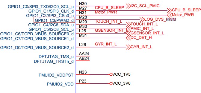
通过硬件原理图确认该 PWM pin 的默认上下拉。例如 RK3399 挖掘机板子 PWM2 作为调压功能,在原理图上找到 PWM2 pin 脚: GPIO1_C3/PWM2_d,其中的"d"表示 down 为默认下拉;如果是"u"表示 up 默认上拉。
dtsi 中定义 PWM pull down pinctrl:
pwm2_pin_pull_down: pwm2-pin-pull-down {
   rockchip,pins =
   <1 19 RK_FUNC_1 &pcfg_pull_down>;
};
在 dts 中重新 PWM 覆盖 pinctrl:
&pwm2 {
  status = "okay";
  pinctrl-names = "active";
  pinctrl-0 = <&pwm2_pin_pull_down>;
};
4.3 PWM 波形无法示波器测到
如果示波器测试不到波形,从两方面入手:
先检查 PWM Counter Register 寄存器的值是否在变化,如果有变化说明 PWM 在工作 (注意,如果用 io 命令来读取寄存器,在产品文档的表格中 RK3328 和它之后的芯片需要再关闭 pclk 的 gating,因为这些芯片 pclk 和工作时钟是分开的);如果该寄存器的值没有发生变化,则说明 PWM 工作异常。一般,这些异常分为以下几个方面:
时钟问题;
PWM 本身寄存器配置问题,PWM 未使能或者 duty 配置的值大于 period 等;
RK3368 芯片需要额外配置 GRF 中 GRF_SOC_CON15 寄存器的 bit12 为 1。
如果读出来的 Counter Register 寄存器的值在发生变化,则说明 PWM 工作正常,但是仍量不到信号,应该是 pin 脚的问题,一般也分为以下几个可能:
iomux 问题;
io-domain 配置不对;
被外面硬件干扰。